| Issue |
Dairy Sci. Technol.
Volume 90, Number 2-3, March–June 2010
Special Issue: Selected papers from 4th International Symposium on Spray Dried Dairy Products, 15-17th April 2009, Melbourne, Australia |
|
|---|---|---|
| Page(s) | 321 - 334 | |
| DOI | https://doi.org/10.1051/dst/2010013 | |
| Published online | 30 March 2010 | |
Original article
Spray-freeze-drying of whey proteins at sub-atmospheric pressures
低压下乳清蛋白的冷冻喷雾干燥
Couplage du séchage par pulvérisation et de la lyophilisation de protéines de lactosérum à pressions sous-atmosphériques
1
Department of Chemical Engineering, Loughborough University, Loughborough, Leicestershire, LE11 3TU, UK
2
Present address: Central Food Technological Research Institute, Mysore, India
* Corresponding author (通讯作者): This email address is being protected from spambots. You need JavaScript enabled to view it.
Received:
11
April
2009
Revised:
3
January
2010
Accepted:
11
February
2010
Abstract
Spray-freeze-drying (SFD) involves spraying a solution into a cold medium, and freeze-drying the resultant frozen particles, which can be performed by contacting the particles with a cold, dry gas stream in a fluidized bed, typically at atmospheric pressure. This enables much faster drying rates than are usually possible by conventional freeze-drying, due to the small particle sizes involved. However, the quantities of gas required for atmospheric fluidized bed freeze-drying are prohibitively expensive. This has led to a process modification whereby fluidization is performed at sub-atmospheric pressures, which still allows rapid freeze-drying, but using much less gas. This study demonstrates the fluidized bed SFD technique at sub-atmospheric pressures (0.1 bar) using whey protein isolate solution (20% w/w solids) at gas inlet drying temperatures ranging from −10 °C to −30 °C. The process yields a powder consisting of highly porous particles and shows little loss of solubility for β-lactoglobulin and α-lactalbumin, the principal proteins in the isolate. A wet basis moisture content of 8.1% was achieved after freeze-drying at −10 °C for only 1 h, while at 30 °C a longer drying time (100 min) produced a wetter product (14% w.b.).
摘要
摘要 冷冻喷雾干燥是将溶液喷雾到冷的介质中然后冷冻干燥形成冷冻的颗粒,这个过程通常是在常压下物料在流化床上与冷的干燥气流接触后完成的。由于这个过程中物料的颗粒非常小,使得干燥速度比常规的冷冻干燥速度快。然而,常压流化床冷冻干燥所需要气体的数量非常大使得生产成本大大提高。这就促使人们将常压流化床改为低压流化床,因为在低压下采用较少量的气体就可以达到同样的快速冷冻干燥。本研究证明了在进口干燥气体的温度为 −10 °C ~ −30 °C 和 0.1 bar 的低压下完成乳清分离蛋白冷冻喷雾干燥的可能性。研究证明该干燥工艺过程得到的乳清蛋白粉颗粒具有非常高的多孔性,而且对 β-乳球蛋白和 α-乳白蛋白溶解性的损失也非常小。在 −10 °C 下只要冷冻 1 h,乳清蛋白粉的水分就达到了8.1% (干基),而在 −30 °C 时,则需要 100 min 水分含量才达到了14% (干基).
Résumé
Le couplage du séchage par pulvérisation et de la lyophilisation implique la pulvérisation d’une solution à travers un milieu froid et la lyophilisation des particules congelées obtenues, qui peut être réalisée par contact avec un fluide gazeux froid et sec dans un lit fluidisé, classiquement à pression atmosphérique. Cela permet des vitesses de séchage beaucoup plus élevées que celles obtenues par lyophilisation conventionnelle, en raison de la petite taille des particules impliquées. Cependant, les quantités de gaz requises pour la lyophilisation sur lit fluidisé à pression atmosphérique sont excessivement onéreuses, ce qui a conduit à modifier le procédé de façon à réaliser la fluidisation à pression sous-atmosphérique. La lyophilisation est ainsi toujours rapide, mais moins consommatrice de gaz. Cette étude présente la technique de séchage par pulvérisation-lyophilisation sur lit fluidisé à pression sous-atmosphérique (0,1 bar) d’une solution d’isolat de protéine de lactosérum (20 % p/p) pour des températures de gaz à l’entrée du séchage comprises entre −10 et −30 °C. Le procédé produit une poudre composée de particules hautement poreuses et montre une légère perte de solubilité de la β-lactoglobuline et de l’α-lactalbumine, les principales protéines contenues dans l’isolat. Une teneur en humidité de 8,1 % sur base humide était obtenue après séchage par lyophilisation à −10 °C après seulement une heure, alors qu’un produit plus humide (14 % sur base humide) était obtenu à −30 °C après un temps plus long (100 min).
Key words: fluidization / lyophilization / particulate / milk protein
关键字 : 流化床 / 冻干法 / 颗粒 / 牛奶
Mots clés : fluidisation / lyophilisation / particulation / protéine laitière
© INRA, EDP Sciences, 2010
1. INTRODUCTION
Freeze-drying is a popular method of producing shelf stable particulate products, and is of particular value for drying thermally sensitive materials (usually biologically based), which can be heat damaged by higher temperature methods, such as spray-drying. Porous structures are formed by the creation of ice crystals during the freezing stage, which subsequently sublime during the drying stage and this often leads to good rehydration behaviour of the powdered product [20]. However, freeze-drying involves high capital and operating costs, due to the low temperatures, high vacuum and long residence times required. It has been found that freeze-drying times vary approximately with the square of the sample thickness [8, 13]. Hence, one solution to this problem of long residence times is to reduce the dimensions of the material, i.e. use smaller particle sizes. This is the basis of the spray-freeze-drying (SFD) technique, which is a two-step process of (i) spray-freezing followed by (ii) freeze-drying. Spray-freezing involves the atomization of a liquid stream in a manner similar to spray-drying, but then freezing the spray. At present, three classes of methods are used for spray-freezing: (i) spray-freezing into vapour (SFV) [10, 21], (ii) spray-freezing into vapour over liquid (SFV/L) [12, 17] and (iii) spray-freezing into liquid (SFL) [5, 18]. The second freeze-drying step is often achieved by conventional freeze-drying, in which the latent heat of sublimation is supplied by conductive or radiative heating. However, this is difficult to apply uniformly to a powder, so as to take advantage of the small particle size and reduced drying times, without the risk of particle melting and collapse. Instead an alternative approach of contacting the articles with cold, dry gas in a fluidized bed can be used.
The concept of freeze-drying using atmospheric air was first published in the 1950s [14], but the use of a fluidized bed is more recent [13] and does not appear yet to have had widespread application to freeze-dry powders. The majority of published work on SFD has been in the pharmaceutical area where freeze-drying has been performed conventionally on trays. An exception has been the work of Mumenthaler and Leuenberger [10, 15] and later Wang et al. [21] who used cold desiccated gas to first freeze and then dry the spray in an integrated fluidized bed at atmospheric pressure. This process is able to work by maintaining a very low dew point of water within the system, which allows ice to sublime even at atmospheric pressure. Due to the small particle sizes, drying times of 2 h were able to be achieved.
A problem with the atmospheric SFD process, however, is the very large quantities of cold dry gas that need to be circulated through the bed. As freeze-drying must be performed below the collapse temperature of the material (which can be as low as –30 °C), the ice phase exerts an extremely low vapour pressure (e.g. 38.96 Pa at –30 °C). Even if freeze-drying had a negligible resistance for mass transfer from within the particle to the gas phase (such that the exit gas of the fluidized bed was at the saturation value of the particle temperature), from the Ideal Gas Law it would require ~ 4200 kg of bone dry gas to pass through the bed in order to sublime 1 kg of ice. Although this can be partly offset by recirculating (and drying) the gas, this is a huge quantity of gas that has to be supplied to the process. The refrigeration and drying requirements for such a mass of gas to meet the required specification are considerable and severely harm the economics of the process. A further consideration is that to pass this mass of gas through the bed in a reasonable time (say a few hours) requires a very large gas volume flow rate and hence a high velocity in the fluidized bed. This leads to particles being elutriated and subsequently these must be caught by a gas filter, as reported by Mumenthaler and Leuenberger [15]. Although this is a feasible means of drying the particles, it does render the fluidized bed (with its high heat and mass transfer capability) redundant.
1.1. Sub-atmospheric SFD
One means of alleviating the problem of circulating large mass flow rates of dry gas, which has recently been considered in the literature, is to apply a partial vacuum to the process [1, 11]. The gas is, after all, merely an inert heat transfer medium and plays no part in determining the driving force for mass transfer. As an example, if the process is operated at –30 °C and an absolute pressure of 0.1 bar, then the mass of saturated gas required would be ~ 420 kg (i.e. one tenth of the amount at 1 bar). Although vacuum capability increases the capital cost and operational difficulty of the plant, it also significantly reduces the mass of dry gas required. An initially rather startling result is that the volume of inert gas to sublime 1 kg of ice (assuming saturation) is independent of the system pressure (in the above examples, ~ 2900 m3 of gas would be required in both cases). This is because even though there is tenfold reduction in the mass of gas required at 0.1 bar, the reduction in pressure by a factor of 10 means that the gas is also 10 times less dense. By the same token to extract this 1 kg of ice, the gas velocity passing through the bed would also be the same irrespective of total system pressure. However, the lower density at lower pressures would reduce the inertial (non-viscous) drag forces on the particles, and if a low enough pressure were used then particles would not be elutriated from the bed.
Thus, lower pressures are desirable as they decrease the mass of gas required and reduce the number of particles being swept from the bed. This might suggest approaching the pressures used in conventional freeze-drying (with effectively no gas in the system); however, enough gas needs to be present to supply the latent heat of sublimation.
In this study, a SFD rig has been constructed, in which the fluidized bed freeze-drying section is capable of operating at reduced pressures [1], as shown in Figure 1. The fluidized bed is fitted with thermocouples to measure the temperatures of the particle bed and the exit gas (located ~ 3 cm above the bed). These provide a measurement of the “wet-bulb” depression of the particles, and thus provide an indication of the drying rate. The process is demonstrated by SFD a solution of whey protein isolate (WPI).
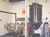 |
Figure 1. The SFD apparatus used in these experiments. Spray-freezing initially occurs in the large (black) chamber located on the right of the photograph. The spray frozen particles are collected from the base of this chamber and transferred to the sub-atmospheric fluidized bed freeze-drying apparatus on the left of the photograph. |
2. MATERIALS AND METHODS
2.1. Whey protein solution preparation
Whey protein isolate powder was obtained from Ultimate Nutrition (Fleetwood, Lancashire, UK), and the manufacturer claims that 99% of the whey proteins are undenatured. The 20% (w/v) whey protein solution was prepared at room temperature by dissolving 200 g of powder in 0.7 L distilled water. This mixture was gently stirred in a laboratory mixer (Silverson) for 10 min to dissolve all the whey proteins in water and finally made up to 1 L by the addition of distilled water. The mixture was kept for a consistent period of 30 min before SFD, in order for the protein to hydrate.
2.2. SFD equipment
The SFD system used here differs from that of Leuenberger’s group [11, 15], in that spray-freezing and freeze-drying are carried out in two separate vessels. Spray frozen particles are first formed by spraying the concentrate into a cooled spray chamber (1.5 m high × 0.8 m diameter). The chamber had been previously purged with nitrogen gas from a cylinder before cooling with liquid nitrogen from a dewar. The spray chamber wall temperature and gas temperature were then adjusted to –85 ± 2 °C by regulating the nitrogen flowrate. Atomization was achieved with a hydraulic nozzle (WL053 ex Bete, Lewes, UK) using a liquid feed from a feed tank pressurized with nitrogen gas at 8 bar gauge pressure. To avoid the liquid feed freezing in the nozzle, the nozzle and approaching pipework were kept warm by circulating warm air around them, with only the nozzle tip being exposed to the cold chamber gas. The liquid feed rates were measured for each experiment by measuring the change in volume of feed in the feed vessel over time. The measured liquid feed flow rate for all the trials was 0.0125 kg·s−1. The frozen particles were collected from the outlet of the chamber in a cooled expanded polystyrene box. The particles were then loaded into the freeze-dryer, which consisted of a polycarbonate cylinder inside a stainless steel vacuum vessel (see Fig. 2). The bottom of the polycarbonate cylinder (16 cm high × 15 cm diameter) was fitted with a 2-mm thick polyethylene sheet (Vyon F2, Porvair Technology) to act as a distributor plate and the top of the vessel was fitted with a fine mesh to allow a low temperature gas flow through the particle bed while retaining the particles within the drying chamber.
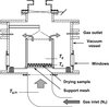 |
Figure 2. Schematic diagram of the sub-atmospheric fluidized bed freeze-dryer. |
As well as offering sub-atmospheric operation the equipment used here does not recycle the gas but uses nitrogen gas (sourced from a liquid nitrogen dewar) in a “once through” configuration. The temperature of the gas (which is warmed as it travels into the rig) is regulated by adjusting the flow rate. The temperatures of the inlet gas, the bed and the fluidizing gas just above the bed were measured by type T thermocouples. The depth of the bed was ~ 1 cm. For the production of freeze-dried whey, a constant inlet gas temperature was used. This resulted in the particle temperatures gradually rising during the drying cycle. A period of 10 min was required in order to stabilize the operating conditions at the beginning of the process (as the particles enter the chamber at a much colder temperature). The chamber was maintained under a partial vacuum using a rotary vane oil-sealed vacuum pump (Werner Rietschle model CLF100, Schopfheim, Germany) at the outlet which delivers a nominal gas flow rate of 100 m3·h−1 through the bed. The chamber pressure was measured using a Druck PMP4070 pressure sensor. All instrumentation was connected via a Datascan 7321 data logger to a PC running DASYLAB data acquisition software. The resulting spray-freeze-dried product was analysed for moisture content, particle size and morphology and the loss of solubility of the proteins.
2.3. Moisture content
The average moisture content of the spray-freeze-dried powder was measured gravimetrically. A known mass of sample (~ 0.5 g) was placed in an aluminium foil pan and dried in a vacuum oven at 105 °C for a period of 12 h. The sample was then removed and immediately weighed to limit water absorption from the atmosphere. The initial and final weights were then used to calculate the wet basis moisture content. The experiments were carried out in triplicate and average and standard deviation (SD) values calculated.
2.4. Particle size
Particle size was determined by a Coulter LS 130 (Beckman Coulter, High Wycombe, Bucks, UK) particle sizer that measures particle sizes in the range of 0.4–800 μm using laser light scattering. Each sample was dispersed in a solvent (isobutanol) to perform the measurements. The particle sizes are presented as Sauter mean diameters (μm), with mean and SD values calculated from three independent measurements.
2.5. Loss of solubility
The amounts of native α-lactalbumin and β-lactoglobulin in the soluble fraction at pH 4.6 were determined by reversed phase high-performance liquid chromatography (RP-HPLC), based on the method of Ferreira et al. [6, 7]. For details of the exact method used, readers are referred to Anandharamakrishnan et al. [4]. The experiments were carried out in triplicate for each sample, and average values were taken to calculate the loss of solubility from the following equation: (1)where SPfd is the soluble protein in the spray-freeze-dried sample and SPu is the soluble protein in the untreated sample.
2.6. Scanning electron microscopy
Scanning electron microscope (SEM) images of the spray-freeze-dried samples were examined using a Cambridge Stereo Scan 360 at the Department of Materials Engineering at Loughborough University, UK.
3. RESULTS AND DISCUSSIONS
3.1. Temperature measurements during freeze-drying
Table I shows drying times, measured final moisture content and average particle size for the three inlet gas temperatures used in this study. In general, the process yields reasonably low moisture contents, but these are achieved considerably faster than the many hours usually required for conventional freeze-drying (such as 40 h for conventionally freeze-drying protein powders [12]). Faster drying rates are observed at higher temperatures with a drying time of only 1 h required to produce a powdered product of 8.1% at –10 °C, whereas at –30 °C a moisture content of only 14% was achieved after 100 min. This is not unsurprising, given the larger transport coefficients and pure ice vapour pressure at the higher temperatures. The drying times observed here compare favourably with those previously reported in the literature [11, 15] for trehalose and mannitol.
Effects of inlet gas temperatures of fluidized bed freeze dryer on moisture content, particle size and drying times. The error data represent 1 SD from the mean.
Figure 3 shows inlet gas, outlet gas and particle bed temperatures for an example run operating at an absolute system pressure of 0.1 bar and at a constant gas inlet temperature of –10 °C. A visual inspection of the bed showed very mild fluidization to be taking place. It can be seen that there is a significant wet-bulb depression of the particle temperature below the gas temperature and a significant change in temperature of the gas as it passes through the bed. It can be seen that these temperature differences reduce as time proceeds. Both indicate that a significant degree of drying is taking place as convective heat transfer from the gas to the particles must be taking place to overcome sublimative cooling.
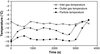 |
Figure 3. Inlet gas, outlet gas and particle temperatures during the freeze-drying of whey at −10 ± 1.0 °C and 0.1 bar. |
Indications from other experiments suggest that the difference between the particle and gas temperatures increases as the system pressure is reduced. This is because the pressure influences the thermal mass of the fluidizing gas and the heat transfer coefficient between the gas and the particle bed. The variation of the rate of drying with time can be inferred from the temperature measurements by assuming that the heat transfer coefficient and heat transfer surface area are constant during drying, i.e. (2)where A is the surface area of the particles, h is the heat transfer coefficient, λ is the latent heat of sublimation, T
p is the particle temperature, M is the mass of sample and T
g is the gas temperature in contact with the particles. This assumes that all the heat supplied is consumed by the latent heat of ice sublimation. The gas temperature T
g needs to be corrected by an amount ΔT
offset obtained at zero drying rate due to warming of gas in the fluidizing chamber
(2)where A is the surface area of the particles, h is the heat transfer coefficient, λ is the latent heat of sublimation, T
p is the particle temperature, M is the mass of sample and T
g is the gas temperature in contact with the particles. This assumes that all the heat supplied is consumed by the latent heat of ice sublimation. The gas temperature T
g needs to be corrected by an amount ΔT
offset obtained at zero drying rate due to warming of gas in the fluidizing chamber (3)
(3)
 (4)
(4)
As the mass of dry whey also remains constant, the above equation can be expressed in terms of the dry basis moisture content, i.e. (5)where
 (6)
(6)
Integrating equation (5) over the whole time of the experiment yields: (7)
(7)
Thus, evaluating the area under the curve of (T g − T p) versus t (see Fig. 4), combined with a knowledge of the initial and final dry basis moisture contents, enables the value of k to be determined.
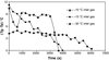 |
Figure 4. Wet-bulb depression (difference of outlet gas and particle temperatures) versus time during the freeze-drying of whey at 0.1 bar. |
Integrating equation (5) to intermediate times yields: (8)
(8)
Equation (8) thus offers a means of obtaining a drying curve of the material under all drying regimes. This assumes that the material in contact with the particle bed thermocouple is representative of the bed as a whole. It also assumes that the thermocouple measuring the “particle” temperature is not influenced by the passing gas temperature. However, it may well be the case that this thermocouple instead provides a weighted mean of the particle and gas temperatures. This would act to reduce the observed temperature difference by a certain proportion which would remain constant if the relative “weights” (comprising the weighted mean) remain reasonably constant. The resulting drying curve would thus be unaffected. However, changes to the relative weightings would affect the overall result and this may occur as a result of changing fluidization behaviour (which becomes more lively towards the end of an experiment). The different behaviour shown by experiments at –10 °C and –30 °C (which show signs of a constant rate period) compared to the experiment at –15 °C (which does not) may be caused by this. Thus, while the method is an effective monitoring tool it should not be relied upon for highly accurate data. The drying curves obtained from this analysis are shown for all three inlet gas temperatures in Figure 5, and it clearly indicates gradually decreasing rates of drying of all runs, as the particle temperatures gradually rise.
3.2. Particle size analysis
The SFD process produces Sauter mean particle diameter particle sizes in the range of 393–489 μm (Tab. I). Larger diameter particles were found when an inlet temperature of –10 °C was used. The particle sizes are larger than expected for this spray [1] and this is a consequence of the collection method which is biased; larger particles are more likely to drop into the collection box rather than be conveyed away on the air stream.
3.3. Solubility analysis
Loss of solubility of α-lactalbumin and β-lactoglobulin was analysed using the RP-HPLC method. The chromatograms for WPI before and after SFD are shown in Figure 6. The chromatograms can clearly resolve the individual peaks for α-lactalbumin and β-lactoglobulin. From the areas of these peaks, it was determined that there was no detectable loss of solubility of α-lactalbumin, whereas a 2 ± 0.5% loss of solubility of β-lactoglobulin was observed after SFD of WPI in all the trials (the variations in the –10, –15 and –30 °C trials are within the experimental error range). Earlier reports also indicated that α-lactalbumin is a more stable protein than β-lactoglobulin [4, 7]. Thus only a mild loss of solubility of proteins occurs during SFD.
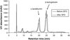 |
Figure 6. RP-HPLC chromatograms of spray-freeze-dried WPI before and after SFD. |
3.4. SEM images of spray-freeze-dried particles
Observing the internal microstructure of the spray-freeze-dried product is a useful means of validating that the dried product has been properly freeze-dried and has not suffered collapse. The external surface composition of the powder can also influence its properties such as solubility, flowability and stickiness. Numerous studies have been performed on the spray-dried powder surface and internal structures [3, 19]. However, very few studies have reported on surface and microstructures of spray-freeze-dried particles. The first particle surface study was performed by Al-Hakim and Stapley [2] with cryo-SEM images of spray-freeze-dried whey protein powders. More complex multi-component milk powders have been recently studied by Hindmarsh et al. [9] and Rogers et al. [16].
SEM images of spray-freeze-dried WPI powder are shown in Figure 7. All three different inlet temperature runs show similar particle morphologies. A typical large particle with smaller particles agglomerated onto its surface is shown in Figure 7(a).
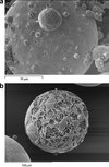 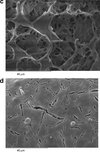 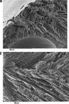 |
Figure 7. SEM images of spray-freeze-dried WPI powder. The widths of the images are 140, 220, 83, 96, 90 and 96 μm, respectively. |
The surfaces of the particles in Figures 7(a), 7(b) and 7(d) are generally smooth, containing small pores and an occasional surface blemish. A magnification of one of these blemishes surface is shown in Figure 7(c), which reveals a porous structure inside the particle. This is to be expected from a freeze-dried product, and is a consequence of ice crystal formation during the freezing step, which sublimes during freeze-drying to leave a porous structure. This confirms that collapse has not occurred during freeze-drying. Due to the very fast rates of freezing at this size scale, the ice crystals – and hence pore sizes – are much smaller than normally found in freeze-dried products. Figure 7(c) shows this at greater magnification, whereas Figures 7(e) and 7(f) shows the internal pore structure from some particles which have fragmented. These microstructures are similar to those found by Hindmarsh et al. [9] and Rogers et al. [16]. Figure 7(e) shows a bubble inside a particle. The bubble is probably the result of nitrogen gas being releasing from solution during atomization, as the feed solution is held under pressure using compressed nitrogen in the feed chamber. Yu et al. [22] also reported that small bubbles were generated during atomization and they observed that bubbles were presented in the particles during SFV/L process.
4. CONCLUSIONS
The results presented here show that the SFD technique has been shown to work well, by performing the freeze-drying step at sub-atmospheric pressures (0.1 bar absolute). Not only has rapid drying been obtained (of the time scale of 1 h), but the particles were not eluted from the fluidized bed and a significantly smaller mass of gas was used than would have been the case if operated at atmospheric pressure. Dryer particle could probably be obtained if the inlet gas temperature is raised towards the end of the experimental run (assuming the particles have dried sufficiently to avoid collapse as the temperature is raised).
Temperature measurements of the particles and the gas show a significant cooling of the particles below the gas temperature (wet-bulb effect). This gradually diminishes during drying and can be used to construct a drying curve. While not necessarily providing a highly accurate measurement of drying, it is shown to be effective as a monitoring tool. The wet-bulb depression is dependent on system pressure and rises as the pressure is reduced. This study also indicates that highest temperature run (–10 °C) produces the greatest drying rate. The resulting product is highly porous and suffers little loss of protein solubility for β-lactoglobulin. In this research scale experimental rig the gas is not recycled and this limits the sample mass to a few grams. Larger quantities could be produced using a system for recycling the drying gas as performed by Leuenberger’s group [11, 15]. Scale-up of the process is likely to be complicated by the probable need to maintain a shallow bed meaning that very large bed areas would be required to produce quantities in a commercial scale. Nevertheless, the technique appears to be able to produce powdered pharmaceutical and food products more quickly than is normally possible by vacuum freeze-drying processes, although each process is limited by different factors.
Acknowledgments
We gratefully acknowledge the Commonwealth Scholarship Commission, UK for the award of Commonwealth Scholarship to CA. We also wish to acknowledge the EPSRC (UK) for funding the development of the experimental rig (Grant No. GR/N16662).
References
- Al-Hakim K., An Investigation of Spray-Freezing and Spray-Freeze-Drying, Ph.D. Thesis, Loughborough University, UK, 2004. [Google Scholar]
- Al-Hakim K., Stapley A.G.F., Morphology of spray-dried and spray-freeze-dried whey powders, in Proceedings of the 14th International Drying Symposium, 22–25 August 2001, Drying 2004, São Paulo, Brazil, pp. 1720–1726. [Google Scholar]
- Anandharamakrishnan C., Rielly C.D., Stapley A.G.F., Effects of process variables on the denaturation of whey proteins during spray-drying, Drying Technol. 25 (2007) 799–807. [CrossRef] [Google Scholar]
- Anandharamakrishnan C., Rielly C.D., Stapley A.G.F., Loss of solubility of α-lactalbumin and β-lactoglobulin during spray drying of whey proteins, LWT-Food Sci. Technol. 41 (2008) 270–277. [CrossRef] [Google Scholar]
- Costantino H.R., Firouzabadian L., Hogeland K., Wu C., Beganski C., Carrasquillo K.G., Cordova M., Griebenow K., Zale S.E., Tracy M.A., Protein spray-freeze-drying-effect of atomization condition on particle size and stability, Pharm. Res. 17 (2000) 1374–1380. [CrossRef] [PubMed] [Google Scholar]
- Ferreira I.M.P.L.V.O., Cacote H., Detection and quantification of bovine, ovine and caprine milk percentage in protected denomination of origin cheese by reversed-phase high-performance liquid chromatography of beta-lactoglobulins, J. Chromatogr. A. 1015 (2003) 111–118. [CrossRef] [PubMed] [Google Scholar]
- Ferreira I.M.P.L.V.O., Mendes E., Ferreira M.A., HPLC/UV analysis of protein in dairy products using a hydrophobic interaction chromatographic column, Anal. Sci. 17 (2001) 499–501. [CrossRef] [PubMed] [Google Scholar]
- Heldman D.R., An analysis of atmospheric freeze-drying, J. Food Sci. 39 (1974) 147–155. [CrossRef] [Google Scholar]
- Hindmarsh J.P., Russell A.B., Chen X.D., Fundamentals of the spray-freezing of foods-microstructure of frozen droplets, J. Food Eng. 78 (2007) 136–150. [CrossRef] [Google Scholar]
- Leuenberger H., Spray-freeze-drying – the process of choice for low water soluble drugs?, J. Nanoparticle Res. 4 (2002) 111–119. [CrossRef] [Google Scholar]
- Leuenberger H., Plitzko M., Puchkov M., Spray-freeze-drying in a fluidized bed at normal and low pressure, Drying Technol. 24 (2006) 711–719. [CrossRef] [Google Scholar]
- Maa Y.F., Nguyen P.A., Sweeney T., Shire S.J., Hsu C.C., Protein inhalation powders: spray drying vs spray-freeze-drying, Pharm. Res. 16 (1999) 249–255. [CrossRef] [PubMed] [Google Scholar]
- Malecki G.J., Shinde P., Morgan A.I., Farkas D.F., Atmospheric fluidized bed freeze-drying, Food Technol. 24 (1970) 601–603. [Google Scholar]
- Meryman H.T., Sublimation freeze-drying without vacuum, Science 130 (1959) 628–629. [CrossRef] [PubMed] [Google Scholar]
- Mumenthaler M., Leuenberger H., Atmospheric spray-freeze-drying: a suitable alternative in freeze-drying technology, Int. J. Pharm. 72 (1991) 97–110. [CrossRef] [Google Scholar]
- Rogers S., Wu W.D., Saunders J., Chen X.D., Characteristics of milk powders produced by spray-freeze-drying, Drying Technol. 26 (2008) 404–412. [Google Scholar]
- Rogers T.L., Hu J., Yu Z., Johnston K.P., Williams III R.O., A novel particle engineering technology: spray-freezing into liquid, Int. J. Pharm. 24 (2002) 93–100. [CrossRef] [Google Scholar]
- Rogers T.L., Nelsen A.C., Sarkari M., Young T.J., Johnston K.P., Williams III R.O., Enhanced aqueous dissolution of poorly water soluble drug by novel particle engineering technology: spray-freezing into liquid with atmospheric freeze-drying, Pharm. Res. 20 (2003) 485–493. [CrossRef] [PubMed] [Google Scholar]
- Sheu T.Y., Rosenberg M., Microstructure of microparticles consisting of whey proteins and carbohydrates, J. Food Sci. 63 (1998) 491–494. [CrossRef] [Google Scholar]
- Stapley A.G.F., Freeze-drying, in: Evans J.A.(Ed.), Frozen Food Science and Technology, Blackwell, Oxford, UK, 2008, pp. 248–275. [CrossRef] [Google Scholar]
- Wang Z.L., Finlay W.H., Peppler M.S., Sweeney L.G., Powder formation by atmospheric spray-freeze-drying, Powder Technol. 170 (2006) 45–52. [CrossRef] [Google Scholar]
- Yu Z., Garcia A.S., Johnston K.P., Williams R.O., Spray-freezing into liquid versus spray-freeze-drying: influence of atomization on protein aggregation and biological activity, Eur. J. Pharm. Biopharm. 27 (2006) 9–18. [Google Scholar]
All Tables
Effects of inlet gas temperatures of fluidized bed freeze dryer on moisture content, particle size and drying times. The error data represent 1 SD from the mean.
All Figures
|
Figure 1. The SFD apparatus used in these experiments. Spray-freezing initially occurs in the large (black) chamber located on the right of the photograph. The spray frozen particles are collected from the base of this chamber and transferred to the sub-atmospheric fluidized bed freeze-drying apparatus on the left of the photograph. |
| In the text | |
|
Figure 2. Schematic diagram of the sub-atmospheric fluidized bed freeze-dryer. |
| In the text | |
|
Figure 3. Inlet gas, outlet gas and particle temperatures during the freeze-drying of whey at −10 ± 1.0 °C and 0.1 bar. |
| In the text | |
|
Figure 4. Wet-bulb depression (difference of outlet gas and particle temperatures) versus time during the freeze-drying of whey at 0.1 bar. |
| In the text | |
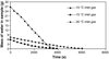 |
Figure 5. Drying curve calculated from the temperature data shown in Figure 4. |
| In the text | |
|
Figure 6. RP-HPLC chromatograms of spray-freeze-dried WPI before and after SFD. |
| In the text | |
|
Figure 7. SEM images of spray-freeze-dried WPI powder. The widths of the images are 140, 220, 83, 96, 90 and 96 μm, respectively. |
| In the text | |